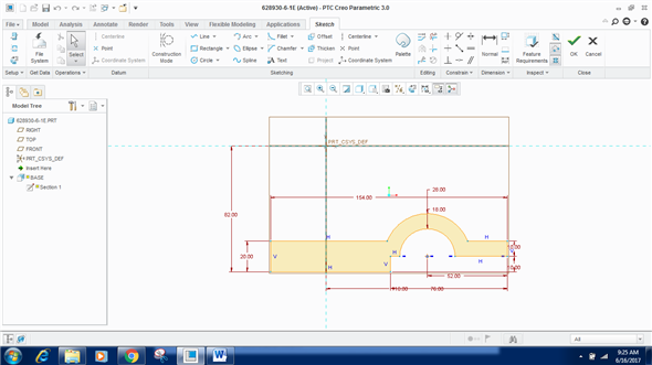

Have the inlet and outlet planes of a porous domain been assigned to separate internal patches? Have the walls been grouped into logical surface-groups easy to maintain during solution and post-processing? Have the areas of the boundaries been checked and matched with the values used to estimate boundary condition parameters? mf for mass-flow, vi for velocity inlets, po for pressure outlets. Have appropriate prefixes been added to the boundary names as per boundary type: e.g. Have the fluid and solid zones named as per material type say by adding air, ss, al, pl, cr (ceramics). Have sliver elements been collapsed? With minimum size ~ 0.05, elements having area < 0.002 or volume 0.0001 are unreasonable. You (and your accounting dept.) will be amazed at the time and budget your team could potentially save, and how much faster you can push products to market.Has the mesh quality been checked for skewness and aspect ratios (for boundary layers and for freestream elements)? Watch the example video to see each of these new features in action. These features in Sketcher give you finer controls, as well as tools to create sketches faster and more accurately. Sketch regions provide users with significant time savings as well as a simple flexible workflow. Adjust the size and color of the constraints to your liking.Ĭombining the sketch regions with depth features gives you a faster workflow that requires fewer overall features. Plus, you’ll find it easier to visualize the display of constraints. Now, Sketcher has more definitions of feature depth, including negative depth values, and depth offset from existing references. Each extrude required its own sketch, too. When combining these sketch regions with multi-body modeling, you can generate geometry for multiple components quickly within a single sketch.Įarlier Sketcher versions required additional datum planes for the location and depth of features. You can create a sketch that consists of multiple regions, and then create new features using portions of that sketch. It all adds up to easier maintenance of imported/draft drawings and a quick organization of 2D draft views. This enhancement also creates relations between several draft views (general-projection view) and shows their hierarchy relation in the drawing tree. This is especially useful for importing legacy drawings that have no model behind them, or when you have a collection of draft entities that you want treated as a single view. Select several entities - created or imported - and convert them all into a scalable 2D draft view. Plus, a shortcut menu option toggles sketched entities between the construction mode and solid mode.Ĭreate a 2D draft view out of draft and imported entities with the Create Draft View option. This mode supports a wider variety of geometries, including construction lines, arcs, rectangles, and more. With Construction mode, you can sketch reference geometry with phantom lines before you create the final geometry.


Realizing design intent is fast and accurate.
#CREO SKETCH TO GMSH FULL#
When sketching with these new tools, take full control of the snapping guides when snapping to draft entities or to model geometry.

Quick, precise definitions for sketched geometry save you time when it comes to applying those early design changes. Use the dimension toolbar to set dimension schemes and references. Dragging behavior is intuitive with on-the-fly dimension definition, creating a smooth Drawing Mode experience. With modernized drawing tools in Sketcher, you can create non-parametric geometry like lines, arcs, rectangles, circles, ellipses, splines, and points.


 0 kommentar(er)
